Senin, 20 Februari 2017

Minggu, 12 Februari 2017
IC 555 Timer Tester
Raj K. Gorkhali
This
simple and easy-to-use gadget not only tests the IC 555 timer in all
its basic configurations but also tests the functionality of each pin of
the timer. Once a timer is declared fit by this gadget, it will
function satisfactorily in whatever mode or configuration you may try
it.
The two basic configurations in which a timer IC 555 can be used are the astable and the monostable modes of operation.

When
the DPDT switch (S2) is in position 1-1, the timer under test
automatically gets wired as a monostable multivibrator. In this case,
the monoshot can be triggered by the microswitch (S1). The debouncing
circuit constituted by the two NAND gates of IC1 (N1 and N2) produces a
clean rectangular pulse when the microswitch is pressed. Resistor R3,
capacitor C1 and diode D1 ensure that the trigger terminal of timer IC
555 (pin 2 is the trigger terminal) gets the desired positive-to-ground
trigger pulse. This differentiator circuit also ensures that the width
of the trigger pulse is less than the expected monoshot output pulse.
gadget sederhana dan mudah digunakan ini tidak hanya menguji IC 555 timer dalam semua konfigurasi dasar, tetapi juga menguji fungsi dari setiap pin dari timer. Setelah timer dinyatakan fit oleh gadget ini, itu akan berfungsi secara memuaskan dalam mode atau konfigurasi apa pun yang Anda mungkin mencobanya.
dua konfigurasi dasar di mana timer IC 555 dapat digunakan adalah astabil dan mode monostable operasi.
EFY KONFERENSI DIUMUMKAN!
Ketika saklar DPDT (S2) berada di posisi 1-1, timer yang diuji secara otomatis akan kabel sebagai multivibrator monostable. Dalam hal ini, monoshot dapat dipicu oleh microswitch (S1). Rangkaian debouncing dibentuk oleh dua gerbang NAND dari IC1 (N1 dan N2) menghasilkan pulsa persegi panjang bersih ketika microswitch ditekan. Resistor R3, kapasitor C1 dan dioda D1 memastikan bahwa terminal memicu timer IC 555 (pin 2 adalah terminal pemicu) mendapat yang diinginkan positif-ke-darat memicu pulsa. Sirkuit pembeda ini juga memastikan bahwa lebar pemicu pulsa kurang dari yang diharapkan keluaran monoshot pulsa.
dua konfigurasi dasar di mana timer IC 555 dapat digunakan adalah astabil dan mode monostable operasi.
EFY KONFERENSI DIUMUMKAN!
Ketika saklar DPDT (S2) berada di posisi 1-1, timer yang diuji secara otomatis akan kabel sebagai multivibrator monostable. Dalam hal ini, monoshot dapat dipicu oleh microswitch (S1). Rangkaian debouncing dibentuk oleh dua gerbang NAND dari IC1 (N1 dan N2) menghasilkan pulsa persegi panjang bersih ketika microswitch ditekan. Resistor R3, kapasitor C1 dan dioda D1 memastikan bahwa terminal memicu timer IC 555 (pin 2 adalah terminal pemicu) mendapat yang diinginkan positif-ke-darat memicu pulsa. Sirkuit pembeda ini juga memastikan bahwa lebar pemicu pulsa kurang dari yang diharapkan keluaran monoshot pulsa.

The
monoshot output pulse width is a function of the series combination of
resistor R8 and potentiometer VR2, and capacitor C4. When DPDT switch S2
is in position 2-2, the timer gets configured for the astable mode of
operation. The output is a pulse train with the high time period
determined by the series combination of resistors R8, potentiometer VR2,
resistor R9 and capacitor C4, whereas the low time period is determined
by resistor R9 and capacitor C4.
The
reset terminal of timer IC (pin 4) should be tied to Vcc normally. More
precisely, the voltage at pin 4 should be greater than 0.8V. A voltage
less than that resets the output. Whether you have connected the timer
in the monoshot or astable mode of operation, the output goes low the
moment you bring the reset terminal below 0.8V.
The
control terminal (pin 5) can be used to change the high time (‘on’
time) of the output pulse train in the astable mode and the output pulse
width in the monoshot mode by applying an external voltage. This
external voltage basically changes the reference voltage levels of the
comparators inside the IC. The levels are set by three identical
resistors of usually 5 kilo-ohms inside the IC connected from Vcc to
ground, at 2/3Vcc for pin 5 and 1/3Vcc for pin 2. These levels can be
changed by connecting an external resistor between pin 5 and ground.
Resistor R10 and potentiometer VR3 have been connected for this purpose.
Ketika saklar DPDT (S2) berada di posisi 1-1, timer yang diuji secara otomatis akan kabel sebagai multivibrator monostable. Dalam hal ini, monoshot dapat dipicu oleh microswitch (S1). Rangkaian debouncing dibentuk oleh dua gerbang NAND dari IC1 (N1 dan N2) menghasilkan pulsa persegi panjang bersih ketika microswitch ditekan. Resistor R3, kapasitor C1 dan dioda D1 memastikan bahwa terminal memicu timer IC 555 (pin 2 adalah terminal pemicu) mendapat yang diinginkan positif-ke-darat memicu pulsa. Sirkuit pembeda ini juga memastikan bahwa lebar pemicu pulsa kurang dari yang diharapkan keluaran monoshot pulsa.
Output monoshot lebar pulsa adalah fungsi dari kombinasi rangkaian resistor R8 dan potensiometer VR2, dan kapasitor C4. Ketika DPDT saklar S2 di posisi 2-2, timer akan dikonfigurasi untuk mode astabil operasi. output adalah kereta pulsa dengan periode waktu yang tinggi ditentukan oleh kombinasi seri resistor R8, potensiometer VR2, resistor R9 dan kapasitor C4, sedangkan jangka waktu rendah ditentukan oleh resistor R9 dan kapasitor C4.
Reset terminal IC timer (pin 4) harus diikat ke Vcc normal. Lebih tepatnya, tegangan di pin 4 harus lebih besar dari 0.8V. Sebuah tegangan kurang dari yang ulang output. Apakah Anda telah terhubung timer di monoshot atau mode astabil operasi, output pergi rendah saat Anda membawa ulang terminal bawah 0.8V.
BACA BACA
Electronic Circuit Prototyping More Than Just An Artefact
Kontrol terminal (pin 5) dapat digunakan untuk mengubah waktu tinggi ( 'on' waktu) dari kereta pulsa output dalam modus astabil dan output lebar pulsa dalam modus monoshot dengan menerapkan tegangan eksternal. tegangan eksternal ini pada dasarnya mengubah tingkat tegangan referensi dari pembanding dalam IC. Tingkat ditetapkan oleh tiga resistor identik biasanya 5 kilo-ohm dalam IC terhubung dari Vcc ke ground, pada 2 / 3Vcc untuk pin 5 dan 1 / 3Vcc untuk pin 2. Tingkat ini dapat diubah dengan menghubungkan resistor eksternal antara pin 5 dan tanah. Resistor R10 dan potensiometer VR3 telah terhubung untuk tujuan ini.
Output monoshot lebar pulsa adalah fungsi dari kombinasi rangkaian resistor R8 dan potensiometer VR2, dan kapasitor C4. Ketika DPDT saklar S2 di posisi 2-2, timer akan dikonfigurasi untuk mode astabil operasi. output adalah kereta pulsa dengan periode waktu yang tinggi ditentukan oleh kombinasi seri resistor R8, potensiometer VR2, resistor R9 dan kapasitor C4, sedangkan jangka waktu rendah ditentukan oleh resistor R9 dan kapasitor C4.
Reset terminal IC timer (pin 4) harus diikat ke Vcc normal. Lebih tepatnya, tegangan di pin 4 harus lebih besar dari 0.8V. Sebuah tegangan kurang dari yang ulang output. Apakah Anda telah terhubung timer di monoshot atau mode astabil operasi, output pergi rendah saat Anda membawa ulang terminal bawah 0.8V.
BACA BACA
Electronic Circuit Prototyping More Than Just An Artefact
Kontrol terminal (pin 5) dapat digunakan untuk mengubah waktu tinggi ( 'on' waktu) dari kereta pulsa output dalam modus astabil dan output lebar pulsa dalam modus monoshot dengan menerapkan tegangan eksternal. tegangan eksternal ini pada dasarnya mengubah tingkat tegangan referensi dari pembanding dalam IC. Tingkat ditetapkan oleh tiga resistor identik biasanya 5 kilo-ohm dalam IC terhubung dari Vcc ke ground, pada 2 / 3Vcc untuk pin 5 dan 1 / 3Vcc untuk pin 2. Tingkat ini dapat diubah dengan menghubungkan resistor eksternal antara pin 5 dan tanah. Resistor R10 dan potensiometer VR3 telah terhubung untuk tujuan ini.
The pulse width in the monoshotmode is given by:
1.1×total charging resistance×charging capacitance
1.1×total charging resistance×charging capacitance
This
expression is valid when there is no external resistor connected at pin
5. The pulse width can be reduced by connecting an external resistor.
The high and low time periods in the astable mode are:
High time period = 0.69×chargingresistance×charging capacitance
Low time period = 0.69×dischargeresistance×capacitance
High time period = 0.69×chargingresistance×charging capacitance
Low time period = 0.69×dischargeresistance×capacitance
Again
the expressions are true with no external resistor at pin 5. The high
time period can be made to decrease by connecting an external resistor
between pin 5 and ground.
The circuit can thus be used to check:
1. The timer IC in astable configuration.
2. The timer IC in monostable configuration.
3. The capability of the reset terminal to override all functions and rest the output to low.
4. The function of the control terminal to change the ‘on’ or the ‘high’ time of the output waveform in astable mode of operation and the output pulse width in monostable mode of operation.
1. The timer IC in astable configuration.
2. The timer IC in monostable configuration.
3. The capability of the reset terminal to override all functions and rest the output to low.
4. The function of the control terminal to change the ‘on’ or the ‘high’ time of the output waveform in astable mode of operation and the output pulse width in monostable mode of operation.
The
circuit operates off a 9V battery, which makes the gadget portable. You
can construct it easily on any general-purpose PCB along with the 8-pin
socket.
To test an IC 555:
1. Insert it into the socket.
2. Set switch S2 in position 1-1.
3. Switch on the power supply by flipping switch S3 to ‘on’ position. Power-indicator LED (LED3) glows to indicate that the circuit is ready to test the IC timer.
4. If the IC is okay, LED1 glows because the IC is wired as a monoshot and in the absence of any trigger, its output is low.
5. Apply the trigger pulse by momentarily pressing switch S1. LED1 stops glowing and, in turn, LED2 glows. This confirms that the output of the monoshot has gone high. After the predetermined time period, LED2 goes off and LED1 again glows. Vary preset VR2 and trigger the monoshot again through switch S1. You will find that LED2 glows this time for a longer or a smaller time period depending upon whether you increased or decreased VR2 resistance.
1. Insert it into the socket.
2. Set switch S2 in position 1-1.
3. Switch on the power supply by flipping switch S3 to ‘on’ position. Power-indicator LED (LED3) glows to indicate that the circuit is ready to test the IC timer.
4. If the IC is okay, LED1 glows because the IC is wired as a monoshot and in the absence of any trigger, its output is low.
5. Apply the trigger pulse by momentarily pressing switch S1. LED1 stops glowing and, in turn, LED2 glows. This confirms that the output of the monoshot has gone high. After the predetermined time period, LED2 goes off and LED1 again glows. Vary preset VR2 and trigger the monoshot again through switch S1. You will find that LED2 glows this time for a longer or a smaller time period depending upon whether you increased or decreased VR2 resistance.
6. For checking the reset function of the timer, trigger the monoshot again, and before the expected time is over, quickly decrease the potmeter VR1 resistance so as to bring the voltage at pin 4 below 0.8V. You will observe the output going low (indicated by glowing LED1 and extinguished LED2).
7. For checking the control function of the timer IC, set potmeter VR1 again in the maximum resistance position. Also set preset VR3 in the minimum resistance position. Trigger the monoshot using switch S1. You’ll observe its output going high for a time period that is much less than that determined from the series combination of R8 and VR2, and capacitor C4. In fact, for any fixed setting of this series combination, the output pulse width can be observed to vary for different values of potmeter VR3 resistance—by triggering the monoshot several times, once for each setting of VR3.
8. Now set the DPDT switch in position 2-2. LED1 and LED2 glow alternatively with the timing determined by the resistances in the charge and discharge paths. This means the timer IC is okay and wired in astable mode.
9. The functions of reset and control pins can be checked in astable configuration too in the same way as discussed above for the monoshot configuration.
Ne 555 timer tester
IC 555 Timer Tester
Raj K. Gorkhali
This
simple and easy-to-use gadget not only tests the IC 555 timer in all
its basic configurations but also tests the functionality of each pin of
the timer. Once a timer is declared fit by this gadget, it will
function satisfactorily in whatever mode or configuration you may try
it.
The two basic configurations in which a timer IC 555 can be used are the astable and the monostable modes of operation.
When
the DPDT switch (S2) is in position 1-1, the timer under test
automatically gets wired as a monostable multivibrator. In this case,
the monoshot can be triggered by the microswitch (S1). The debouncing
circuit constituted by the two NAND gates of IC1 (N1 and N2) produces a
clean rectangular pulse when the microswitch is pressed. Resistor R3,
capacitor C1 and diode D1 ensure that the trigger terminal of timer IC
555 (pin 2 is the trigger terminal) gets the desired positive-to-ground
trigger pulse. This differentiator circuit also ensures that the width
of the trigger pulse is less than the expected monoshot output pulse.
gadget sederhana dan mudah digunakan ini tidak hanya menguji IC 555 timer dalam semua konfigurasi dasar, tetapi juga menguji fungsi dari setiap pin dari timer. Setelah timer dinyatakan fit oleh gadget ini, itu akan berfungsi secara memuaskan dalam mode atau konfigurasi apa pun yang Anda mungkin mencobanya.
dua konfigurasi dasar di mana timer IC 555 dapat digunakan adalah astabil dan mode monostable operasi.
EFY KONFERENSI DIUMUMKAN!
Ketika saklar DPDT (S2) berada di posisi 1-1, timer yang diuji secara otomatis akan kabel sebagai multivibrator monostable. Dalam hal ini, monoshot dapat dipicu oleh microswitch (S1). Rangkaian debouncing dibentuk oleh dua gerbang NAND dari IC1 (N1 dan N2) menghasilkan pulsa persegi panjang bersih ketika microswitch ditekan. Resistor R3, kapasitor C1 dan dioda D1 memastikan bahwa terminal memicu timer IC 555 (pin 2 adalah terminal pemicu) mendapat yang diinginkan positif-ke-darat memicu pulsa. Sirkuit pembeda ini juga memastikan bahwa lebar pemicu pulsa kurang dari yang diharapkan keluaran monoshot pulsa.
dua konfigurasi dasar di mana timer IC 555 dapat digunakan adalah astabil dan mode monostable operasi.
EFY KONFERENSI DIUMUMKAN!
Ketika saklar DPDT (S2) berada di posisi 1-1, timer yang diuji secara otomatis akan kabel sebagai multivibrator monostable. Dalam hal ini, monoshot dapat dipicu oleh microswitch (S1). Rangkaian debouncing dibentuk oleh dua gerbang NAND dari IC1 (N1 dan N2) menghasilkan pulsa persegi panjang bersih ketika microswitch ditekan. Resistor R3, kapasitor C1 dan dioda D1 memastikan bahwa terminal memicu timer IC 555 (pin 2 adalah terminal pemicu) mendapat yang diinginkan positif-ke-darat memicu pulsa. Sirkuit pembeda ini juga memastikan bahwa lebar pemicu pulsa kurang dari yang diharapkan keluaran monoshot pulsa.
The
monoshot output pulse width is a function of the series combination of
resistor R8 and potentiometer VR2, and capacitor C4. When DPDT switch S2
is in position 2-2, the timer gets configured for the astable mode of
operation. The output is a pulse train with the high time period
determined by the series combination of resistors R8, potentiometer VR2,
resistor R9 and capacitor C4, whereas the low time period is determined
by resistor R9 and capacitor C4.
The
reset terminal of timer IC (pin 4) should be tied to Vcc normally. More
precisely, the voltage at pin 4 should be greater than 0.8V. A voltage
less than that resets the output. Whether you have connected the timer
in the monoshot or astable mode of operation, the output goes low the
moment you bring the reset terminal below 0.8V.
Output monoshot lebar pulsa adalah fungsi dari kombinasi rangkaian
resistor R8 dan potensiometer VR2, dan kapasitor C4. Ketika DPDT saklar
S2 di posisi 2-2, timer akan dikonfigurasi untuk mode astabil operasi.
output adalah kereta pulsa dengan periode waktu yang tinggi ditentukan
oleh kombinasi seri resistor R8, potensiometer VR2, resistor R9 dan
kapasitor C4, sedangkan jangka waktu rendah ditentukan oleh resistor R9
dan kapasitor C4.
Reset terminal IC timer (pin 4) harus diikat ke Vcc normal. Lebih tepatnya, tegangan di pin 4 harus lebih besar dari 0.8V. Sebuah tegangan kurang dari yang ulang output. Apakah Anda telah terhubung timer di monoshot atau mode astabil operasi, output pergi rendah saat Anda membawa ulang terminal bawah 0.8V.
Reset terminal IC timer (pin 4) harus diikat ke Vcc normal. Lebih tepatnya, tegangan di pin 4 harus lebih besar dari 0.8V. Sebuah tegangan kurang dari yang ulang output. Apakah Anda telah terhubung timer di monoshot atau mode astabil operasi, output pergi rendah saat Anda membawa ulang terminal bawah 0.8V.
The
control terminal (pin 5) can be used to change the high time (‘on’
time) of the output pulse train in the astable mode and the output pulse
width in the monoshot mode by applying an external voltage. This
external voltage basically changes the reference voltage levels of the
comparators inside the IC. The levels are set by three identical
resistors of usually 5 kilo-ohms inside the IC connected from Vcc to
ground, at 2/3Vcc for pin 5 and 1/3Vcc for pin 2. These levels can be
changed by connecting an external resistor between pin 5 and ground.
Resistor R10 and potentiometer VR3 have been connected for this purpose.
BACA BACA
Electronic Circuit Prototyping More Than Just An Artefact
Kontrol terminal (pin 5) dapat digunakan untuk mengubah waktu tinggi ( 'on' waktu) dari kereta pulsa output dalam modus astabil dan output lebar pulsa dalam modus monoshot dengan menerapkan tegangan eksternal. tegangan eksternal ini pada dasarnya mengubah tingkat tegangan referensi dari pembanding dalam IC. Tingkat ditetapkan oleh tiga resistor identik biasanya 5 kilo-ohm dalam IC terhubung dari Vcc ke ground, pada 2 / 3Vcc untuk pin 5 dan 1 / 3Vcc untuk pin 2. Tingkat ini dapat diubah dengan menghubungkan resistor eksternal antara pin 5 dan tanah. Resistor R10 dan potensiometer VR3 telah terhubung untuk tujuan ini.
Electronic Circuit Prototyping More Than Just An Artefact
Kontrol terminal (pin 5) dapat digunakan untuk mengubah waktu tinggi ( 'on' waktu) dari kereta pulsa output dalam modus astabil dan output lebar pulsa dalam modus monoshot dengan menerapkan tegangan eksternal. tegangan eksternal ini pada dasarnya mengubah tingkat tegangan referensi dari pembanding dalam IC. Tingkat ditetapkan oleh tiga resistor identik biasanya 5 kilo-ohm dalam IC terhubung dari Vcc ke ground, pada 2 / 3Vcc untuk pin 5 dan 1 / 3Vcc untuk pin 2. Tingkat ini dapat diubah dengan menghubungkan resistor eksternal antara pin 5 dan tanah. Resistor R10 dan potensiometer VR3 telah terhubung untuk tujuan ini.
The pulse width in the monoshotmode is given by:
1.1×total charging resistance×charging capacitance
1.1×total charging resistance×charging capacitance
This
expression is valid when there is no external resistor connected at pin
5. The pulse width can be reduced by connecting an external resistor.
The high and low time periods in the astable mode are:
High time period = 0.69×chargingresistance×charging capacitance
Low time period = 0.69×dischargeresistance×capacitance
High time period = 0.69×chargingresistance×charging capacitance
Low time period = 0.69×dischargeresistance×capacitance
Again
the expressions are true with no external resistor at pin 5. The high
time period can be made to decrease by connecting an external resistor
between pin 5 and ground.
The circuit can thus be used to check:
1. The timer IC in astable configuration.
2. The timer IC in monostable configuration.
3. The capability of the reset terminal to override all functions and rest the output to low.
4. The function of the control terminal to change the ‘on’ or the ‘high’ time of the output waveform in astable mode of operation and the output pulse width in monostable mode of operation.
1. The timer IC in astable configuration.
2. The timer IC in monostable configuration.
3. The capability of the reset terminal to override all functions and rest the output to low.
4. The function of the control terminal to change the ‘on’ or the ‘high’ time of the output waveform in astable mode of operation and the output pulse width in monostable mode of operation.
The
circuit operates off a 9V battery, which makes the gadget portable. You
can construct it easily on any general-purpose PCB along with the 8-pin
socket.
To test an IC 555:
1. Insert it into the socket.
2. Set switch S2 in position 1-1.
3. Switch on the power supply by flipping switch S3 to ‘on’ position. Power-indicator LED (LED3) glows to indicate that the circuit is ready to test the IC timer.
4. If the IC is okay, LED1 glows because the IC is wired as a monoshot and in the absence of any trigger, its output is low.
5. Apply the trigger pulse by momentarily pressing switch S1. LED1 stops glowing and, in turn, LED2 glows. This confirms that the output of the monoshot has gone high. After the predetermined time period, LED2 goes off and LED1 again glows. Vary preset VR2 and trigger the monoshot again through switch S1. You will find that LED2 glows this time for a longer or a smaller time period depending upon whether you increased or decreased VR2 resistance.
1. Insert it into the socket.
2. Set switch S2 in position 1-1.
3. Switch on the power supply by flipping switch S3 to ‘on’ position. Power-indicator LED (LED3) glows to indicate that the circuit is ready to test the IC timer.
4. If the IC is okay, LED1 glows because the IC is wired as a monoshot and in the absence of any trigger, its output is low.
5. Apply the trigger pulse by momentarily pressing switch S1. LED1 stops glowing and, in turn, LED2 glows. This confirms that the output of the monoshot has gone high. After the predetermined time period, LED2 goes off and LED1 again glows. Vary preset VR2 and trigger the monoshot again through switch S1. You will find that LED2 glows this time for a longer or a smaller time period depending upon whether you increased or decreased VR2 resistance.
Lebar pulsa di monoshotmode yang diberikan oleh:
1.1 × yang total pengisian perlawanan × pengisian kapasitansi
ungkapan ini berlaku ketika tidak ada resistor eksternal yang terhubung pada pin 5. Lebar pulsa dapat dikurangi dengan menghubungkan resistor eksternal.
Tinggi dan rendah periode waktu dalam modus astabil adalah:
periode waktu tinggi = 0,69 × chargingresistance × pengisian kapasitansi
Rendah jangka waktu = 0.69 × dischargeresistance × kapasitansi
Sekali lagi ekspresi benar tanpa resistor eksternal pada pin 5. Periode waktu yang tinggi dapat dibuat untuk mengurangi dengan menghubungkan resistor eksternal antara pin 5 dan tanah.
sirkuit dengan demikian dapat digunakan untuk memeriksa:
1. IC timer dalam konfigurasi astabil.
2. IC timer dalam konfigurasi monostable.
3. Kemampuan terminal ulang untuk mengesampingkan semua fungsi dan beristirahat output ke rendah.
4. Fungsi terminal kontrol untuk mengubah 'on' atau waktu 'tinggi' dari gelombang keluaran dalam modus astabil operasi dan output lebar pulsa dalam modus monostable operasi.
BACA BACA
kekuatan Pulser
sirkuit beroperasi dari baterai 9V, yang membuat portable gadget. Anda dapat membangun itu dengan mudah pada setiap tujuan umum PCB bersama dengan 8-pin socket.
Untuk menguji IC 555:
1. Masukkan ke dalam soket.
2. Set saklar S2 di posisi 1-1.
3. Hidupkan catu daya dengan membalik saklar S3 ke posisi 'on'. LED Power-indikator (LED3) bersinar untuk menunjukkan bahwa sirkuit siap untuk menguji IC timer.
4. Jika IC baik-baik saja, LED1 bersinar karena IC adalah kabel sebagai monoshot dan tanpa adanya pemicu apapun, output rendah.
5. Terapkan pemicu pulsa oleh sejenak menekan saklar S1. LED1 berhenti bersinar dan, pada gilirannya, LED2 bersinar. Ini menegaskan bahwa output dari monoshot telah pergi tinggi. Setelah periode waktu yang telah ditentukan, LED2 berbunyi dan LED1 lagi bersinar. Bervariasi ditetapkan VR2 dan memicu monoshot lagi melalui switch S1. Anda akan menemukan bahwa LED2 bersinar kali ini untuk lebih lama atau jangka waktu yang lebih kecil tergantung pada apakah Anda meningkat atau menurun perlawanan VR2.
1.1 × yang total pengisian perlawanan × pengisian kapasitansi
ungkapan ini berlaku ketika tidak ada resistor eksternal yang terhubung pada pin 5. Lebar pulsa dapat dikurangi dengan menghubungkan resistor eksternal.
Tinggi dan rendah periode waktu dalam modus astabil adalah:
periode waktu tinggi = 0,69 × chargingresistance × pengisian kapasitansi
Rendah jangka waktu = 0.69 × dischargeresistance × kapasitansi
Sekali lagi ekspresi benar tanpa resistor eksternal pada pin 5. Periode waktu yang tinggi dapat dibuat untuk mengurangi dengan menghubungkan resistor eksternal antara pin 5 dan tanah.
sirkuit dengan demikian dapat digunakan untuk memeriksa:
1. IC timer dalam konfigurasi astabil.
2. IC timer dalam konfigurasi monostable.
3. Kemampuan terminal ulang untuk mengesampingkan semua fungsi dan beristirahat output ke rendah.
4. Fungsi terminal kontrol untuk mengubah 'on' atau waktu 'tinggi' dari gelombang keluaran dalam modus astabil operasi dan output lebar pulsa dalam modus monostable operasi.
BACA BACA
kekuatan Pulser
sirkuit beroperasi dari baterai 9V, yang membuat portable gadget. Anda dapat membangun itu dengan mudah pada setiap tujuan umum PCB bersama dengan 8-pin socket.
Untuk menguji IC 555:
1. Masukkan ke dalam soket.
2. Set saklar S2 di posisi 1-1.
3. Hidupkan catu daya dengan membalik saklar S3 ke posisi 'on'. LED Power-indikator (LED3) bersinar untuk menunjukkan bahwa sirkuit siap untuk menguji IC timer.
4. Jika IC baik-baik saja, LED1 bersinar karena IC adalah kabel sebagai monoshot dan tanpa adanya pemicu apapun, output rendah.
5. Terapkan pemicu pulsa oleh sejenak menekan saklar S1. LED1 berhenti bersinar dan, pada gilirannya, LED2 bersinar. Ini menegaskan bahwa output dari monoshot telah pergi tinggi. Setelah periode waktu yang telah ditentukan, LED2 berbunyi dan LED1 lagi bersinar. Bervariasi ditetapkan VR2 dan memicu monoshot lagi melalui switch S1. Anda akan menemukan bahwa LED2 bersinar kali ini untuk lebih lama atau jangka waktu yang lebih kecil tergantung pada apakah Anda meningkat atau menurun perlawanan VR2.
6. For checking the reset function of the timer, trigger the monoshot again, and before the expected time is over, quickly decrease the potmeter VR1 resistance so as to bring the voltage at pin 4 below 0.8V. You will observe the output going low (indicated by glowing LED1 and extinguished LED2).
7. For checking the control function of the timer IC, set potmeter VR1 again in the maximum resistance position. Also set preset VR3 in the minimum resistance position. Trigger the monoshot using switch S1. You’ll observe its output going high for a time period that is much less than that determined from the series combination of R8 and VR2, and capacitor C4. In fact, for any fixed setting of this series combination, the output pulse width can be observed to vary for different values of potmeter VR3 resistance—by triggering the monoshot several times, once for each setting of VR3.
8. Now set the DPDT switch in position 2-2. LED1 and LED2 glow alternatively with the timing determined by the resistances in the charge and discharge paths. This means the timer IC is okay and wired in astable mode.
9. The functions of reset and control pins can be checked in astable configuration too in the same way as discussed above for the monoshot configuration.
6. Untuk memeriksa fungsi reset timer, memicu monoshot lagi, dan sebelum waktu yang diharapkan adalah lebih, cepat menurunkan potmeter VR1 perlawanan sehingga membawa tegangan pada pin 4 di bawah 0.8V. Anda akan melihat output akan rendah (ditunjukkan dengan bersinar LED1 dan padam LED2).
7. Untuk memeriksa fungsi kontrol timer IC, mengatur potensiometer VR1 lagi di posisi perlawanan maksimal. Juga mengatur ditetapkan VR3 di posisi resistance minimum. Memicu monoshot menggunakan saklar S1. Anda akan melihat output akan tinggi untuk jangka waktu yang jauh kurang dari yang ditentukan dari kombinasi seri R8 dan VR2, dan kapasitor C4. Bahkan, untuk pengaturan tetap kombinasi seri ini, lebar pulsa output dapat diamati bervariasi untuk nilai yang berbeda dari potmeter VR3 perlawanan-dengan memicu monoshot beberapa kali, sekali untuk setiap pengaturan VR3.
8. Sekarang atur saklar DPDT di posisi 2-2. LED1 dan LED2 bersinar alternatif dengan waktu ditentukan oleh resistensi dalam pengisian dan pengosongan jalur. Ini berarti timer IC baik-baik saja dan kabel dalam modus astabil.
9. Fungsi reset dan kontrol pin dapat diperiksa dalam konfigurasi astabil terlalu dalam cara yang sama seperti yang dibahas di atas untuk konfigurasi monoshot.
7. Untuk memeriksa fungsi kontrol timer IC, mengatur potensiometer VR1 lagi di posisi perlawanan maksimal. Juga mengatur ditetapkan VR3 di posisi resistance minimum. Memicu monoshot menggunakan saklar S1. Anda akan melihat output akan tinggi untuk jangka waktu yang jauh kurang dari yang ditentukan dari kombinasi seri R8 dan VR2, dan kapasitor C4. Bahkan, untuk pengaturan tetap kombinasi seri ini, lebar pulsa output dapat diamati bervariasi untuk nilai yang berbeda dari potmeter VR3 perlawanan-dengan memicu monoshot beberapa kali, sekali untuk setiap pengaturan VR3.
8. Sekarang atur saklar DPDT di posisi 2-2. LED1 dan LED2 bersinar alternatif dengan waktu ditentukan oleh resistensi dalam pengisian dan pengosongan jalur. Ini berarti timer IC baik-baik saja dan kabel dalam modus astabil.
9. Fungsi reset dan kontrol pin dapat diperiksa dalam konfigurasi astabil terlalu dalam cara yang sama seperti yang dibahas di atas untuk konfigurasi monoshot.
ne 555 diaplikasikan di amplifier
555 Timer PWM Audio Amplifier
T.A. Babu

The
ubiquitous 555 timer IC handles audio signals in its own pulse-width
modulation (PWM) way. Here, the 555 IC works in astable mode. The
switching frequency can be varied from 65 kHz to 188 kHz. Selection of
PWM frequency depends on the amplitude of the input signal as well as
the load impedance. By adjusting VR1, you can ensure comfortable
listening with low audio distortion.
In
pulse-width modulation, the carrier frequency’s pulse width varies as a
function of the amplitude of the input audio signal. Feedback capacitor
C2 ensures faithful reproduction of the audio signal. An output L-C
filter is the common approach for a reasonable rejection of the carrier
frequencies. For simplicity, it is omitted here. Moreover, the speakers
cannot respond to the high-frequency signal. They respond to the average
DC level modulated with the audio signal that we feed in from the
input. Of course, the audio quality is not as good as that of a
professional system, but it would be definitely an amazing experience to
listen audio through a 555 chip with room-filling volume.
Di mana-mana IC timer 555 menangani sinyal audio sendiri pulse-width modulation nya (PWM) cara. Di sini, 555 IC bekerja dalam modus astabil. Frekuensi switching dapat bervariasi dari 65 kHz ke 188 kHz. Pemilihan frekuensi PWM tergantung pada amplitudo sinyal input serta impedansi beban. Dengan menyesuaikan VR1, Anda dapat memastikan mendengarkan nyaman dengan distorsi audio yang rendah.
Dalam modulasi lebar pulsa, lebar pulsa frekuensi pembawa bervariasi sebagai fungsi dari amplitudo sinyal input audio. Umpan balik kapasitor C2 memastikan reproduksi yang setia dari sinyal audio. Output L-C filter adalah pendekatan umum untuk penolakan yang wajar dari frekuensi pembawa. Untuk mempermudah, itu dihilangkan di sini. Selain itu, pembicara tidak bisa menanggapi sinyal frekuensi tinggi. Mereka menanggapi tingkat DC rata termodulasi dengan sinyal audio yang kita makan di dari input. Tentu saja, kualitas audio tidak sebagus yang dari sistem profesional, tapi akan pasti pengalaman yang luar biasa untuk mendengarkan audio melalui 555 chip dengan volume yang ruang-mengisi.

Impedance
matching at both the input and output is important. So an
input-impedance matching transformer (X1) is used to match the headphone
output of a standard CD player to the input of the 555 amp. 8-ohm, 1W
speakers were used as the load. If designed properly, PWM amplifiers
could give a performance similar to conventional amplifiers. Even higher
efficiency and effortless bass are possible.
EFY note. While
testing this circuit at EFY lab, we had used Supertronix KEC make
matching transformer X1, and the input to the circuit was the audio
output taken from the computer’s headphone out terminal.
Pencocokan impedansi pada kedua input dan output penting. Jadi masukan-pencocokan impedansi transformator (X1) digunakan untuk mencocokkan output headphone dari CD player standar untuk input dari 555 amp. 8-ohm, 1W speaker digunakan sebagai beban. Jika dirancang dengan baik, amplifier PWM bisa memberikan kinerja yang mirip dengan amplifier konvensional. efisiensi yang lebih tinggi dan bass usaha yang mungkin.
Catatan EFY. Sementara pengujian sirkuit ini di laboratorium EFY, kami telah menggunakan Supertronix KEC make pencocokan transformator X1, dan input ke sirkuit adalah output audio yang diambil dari headphone komputer keluar terminal.
Catatan EFY. Sementara pengujian sirkuit ini di laboratorium EFY, kami telah menggunakan Supertronix KEC make pencocokan transformator X1, dan input ke sirkuit adalah output audio yang diambil dari headphone komputer keluar terminal.
aplikasi ne555
This circuit is based on a passive
infrared (PIR) sensor, which automatically switches on a device when
someone comes close to it. It can be used for detection of theft or an
unauthorised person entering a restricted area or building. It can also
turn on lights when someone approaches the area where it is installed.
Applications of this circuit include security systems, corridor lights
and bathroom lights, among others.

Circuit and working
 The
circuit diagram of the motion detector using NE555 timer is shown in
Fig. 1. It is built around 230V AC primary to 9V, 300mA secondary
transformer X1, bridge rectifier DB107 (BR1), 6V voltage regulator 7806
(IC1), timer NE555 (IC2) and a few other components.
The
230V AC mains is stepped down to 9V, 300mA through step-down
transformer X1. Secondary output of X1 goes to bridge rectifier BR1.
Capacitor C1 filters the ripples and the rectified output is given to
regulator 7806 (IC1). IC1 provides 6V regulated DC output to operate the
circuit. LED1 is used as a power-on indicator.
 IC2
is configured in monostable mode. Time period of IC2 is based on
resistor R4 and capacitor C3, which is around ten minutes in this case.
By changing resistor R4 and capacitor C3 you can change the time period
of IC2.
Output pin 3 of IC2 is
connected to the base of relay driver transistor T2. Contacts of relay
RL1 are connected to the load, which could be a CFL or a bulb connected
across CON2.
The PIR sensor is a
pyroelectric device developed for detection of human body infrared
radiations. It has a single output that goes high when a valid motion is
detected. That is, the load is switched on whenever the PIR module
senses a body in motion nearby.
The 555
timer IC is an integral part of electronics projects. Be it a simple
project involving a single 8 bit micro-controller and some peripherals
or a complex one involving system on chips (SoCs), 555 timer working is
involved. These provide time delays, as an oscillator and as a flip-flop
element among other applications.
Introduced
in 1971 by the American company Signetics, the 555 is still in
widespread use due to its low price, ease of use and stability. It is
made by many companies in the original bipolar and low-power CMOS types.
According to an estimate, a billion units were manufactured back in the
year 2003 alone. (That time, only 555 i knew was a cough syrup).
Depending
on the manufacturer, the standard 555 package includes 25 transistors, 2
diodes and 15 resistors on a silicon chip installed in an 8-pin mini
dual-in-line package (DIP-8). Variants consists of combining multiple
chips on one board. However 555 is still the most popular. Let’s look at
the pin diagram to have an idea about the timer IC before we talk about
555 timer working.
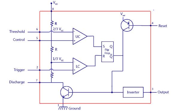
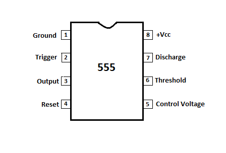
Pin diagram and description
| Pin | Name | Purpose |
| 1 | GND | Ground reference voltage, low level (0 V) |
| 2 | TRIG |
The OUT pin goes high and a timing interval starts when this input falls below 1/2 of CTRL voltage (which is typically 1/3 Vcc, CTRL being 2/3 Vcc by
default if CTRL is left open). In other words, OUT is high as long as
the trigger low. Output of the timer totally depends upon the amplitude
of the external trigger voltage applied to this pin.
|
| 3 | OUT | This output is driven to approximately 1.7 V below +Vcc, or to GND. |
| 4 | RESET |
A
timing interval may be reset by driving this input to GND, but the
timing does not begin again until RESET rises above approximately 0.7
volts. Overrides TRIG which overrides threshold.
|
| 5 | CTRL |
Provides “control” access to the internal voltage divider (by default, 2/3 Vcc).
|
| 6 | THR |
The timing (OUT high) interval ends when the voltage at threshold is greater than that at CTRL (2/3 Vcc if CTRL is open).
|
| 7 | DIS |
Open collector output which may discharge a capacitor between intervals. In phase with output.
|
| 8 | Vcc |
Positive supply voltage, which is usually between 3 and 15 V depending on the variation.
|
Some important features of the 555 timer:
555
is used in almost every electronic circuit today. For a 555 timer
working as a flip flop or as a multi-vibrator, it has a particular set
of configurations. Some of the major features of the 555 would be,
- It operates from a wide range of power ranging from +5 Volts to +18 Volts supply voltage.
- Sinking or sourcing 200 mA of load current.
- The external components should be selected properly so that the timing intervals can be made into several minutes along with the frequencies exceeding several hundred kilo hertz.
- The output of a 555 timer can drive a transistor-transistor logic (TTL) due to its high current output.
- It has a temperature stability of 50 parts per million (ppm) per degree celsius change in temperature which is equivalent to 0.005 %/ °C.
- The duty cycle of the timer is adjustable.
- Also, the maximum power dissipation per package is 600 mW and its trigger and reset inputs has logic compatibility.
555 timer working
The 555 generally operates in 3 modes. A-stable, Mono-stable and Bi-stable modes.
A-stable mode
This
means there will be no stable level at the output. So the output will
be swinging between high and low. This character of unstable output is
used as clock or square wave output for many applications.
Mono-stable mode
This
configuration consists of one stable and one unstable state. The stable
state can be chosen either high or low by the user. If the stable
output is set at high(1), the output of the timer is high(1). At the
application of an interrupt, the timer output turns low(0). Since the
low state is unstable it goes to high(1) automatically after the
interrupt passes. Similar is the case for a low stable mono-stable mode.
Bi-stable mode
In
bi-stable mode, both the output states are stable. At each interrupt,
the output changes from low(0) to high(1) and vice versa, and stays
there. For example, if we have a high(1) output, it will go low(0) once
it receives an interrupt and stay low(0) till the next interrupt changes
the status.
This datasheet should provide an insight into the specifics: 555 Timer IC
induktansi
Inductance
Inductance is the name given to the property of a component that opposes the change of current flowing through it and even a straight piece of wire will have some inductance. Inductors do this by generating a self-induced emf within itself as a result of their changing magnetic field. When the emf is induced in the same circuit in which the current is changing this effect is called Self-induction, ( L ) but it is sometimes commonly called back-emf as its polarity is in the opposite direction to the applied voltage.
When the emf is induced into an adjacent component situated within the same magnetic field, the emf is said to be induced by Mutual-induction, ( M ) and mutual induction is the basic operating principal of transformers, motors, relays etc. Self inductance is a special case of mutual inductance, and because it is produced within a single isolated circuit we generally call self-inductance simply, Inductance. The basic unit of inductance is called the Henry, ( H ) after Joseph Henry, but it also has the units of Webers per Ampere (1 H = 1 Wb/A).
Lenz's Law tells us that an induced emf generates a current in a direction which opposes the change in flux which caused the emf in the first place, the principal of action and reaction. Then we can accurately define Inductance as being "a circuit will have an inductance value of one Henry when an emf of one volt is induced in the circuit were the current flowing through the circuit changes at a rate of one ampere/second". In other words, a coil has an inductance of one Henry when the current flowing through it changes at a rate of one ampere/second inducing a voltage of one volt in it and this definition can be presented as:

induktansi
Induktansi adalah nama yang diberikan untuk properti dari komponen yang menentang perubahan arus yang mengalir melalui itu dan bahkan potongan lurus kawat akan memiliki beberapa induktansi. Induktor melakukan ini dengan menghasilkan emf disebabkan diri dalam dirinya sendiri sebagai akibat dari medan magnet mereka berubah. Ketika emf yang diinduksi di sirkuit yang sama di mana saat ini berubah efek ini disebut Self-induksi, (L) tapi kadang-kadang biasa disebut back-emf sebagai polaritas adalah dalam arah yang berlawanan dengan tegangan yang diberikan.
Ketika emf yang diinduksi menjadi komponen yang berdekatan terletak dalam medan magnet yang sama, ggl yang dikatakan disebabkan oleh Reksa-induksi, (M) dan saling induksi adalah kepala operasi dasar transformator, motor, relay dll Diri induktansi adalah kasus khusus dari induktansi, dan karena diproduksi dalam sirkuit terisolasi tunggal umumnya kita sebut induktansi diri sederhana, Induktansi. Unit dasar induktansi disebut Henry, (H) setelah Joseph Henry, tetapi juga memiliki unit Webers per Ampere (1 H = 1 Wb / A).
Hukum Lenz memberitahu kita bahwa ggl induksi menghasilkan arus dalam arah yang menentang perubahan fluks yang menyebabkan emf di tempat pertama, prinsip aksi dan reaksi. Kemudian kita secara akurat dapat menentukan Induktansi sebagai "sirkuit akan memiliki nilai induktansi dari satu Henry ketika ggl satu volt diinduksi di sirkuit yang saat ini mengalir melalui perubahan sirkuit pada tingkat satu ampere / detik". Dengan kata lain, sebuah kumparan memiliki induktansi dari satu Henry ketika arus yang mengalir melalui perubahan pada tingkat satu ampere / detik menginduksi tegangan satu volt di dalamnya dan definisi ini dapat disajikan sebagai:
Inductance
Inductance, L is actually a measure of an inductors "resistance" to the change of the current flowing through the circuit and the larger is its value in Henries, the lower will be the rate of current change.
We know from the previous tutorial about the Inductor, that inductors are devices that can store their energy in the form of a magnetic field. Inductors are made from individual loops of wire combined to produce a coil and if the number of loops within the coil are increased, then for the same amount of current flowing through the coil, the magnetic flux will also increase. So by increasing the number of loops or turns within a coil, increases the coils inductance. Then the relationship between self-inductance, ( L ) and the number of turns, ( N ) and for a simple single layered coil can be given as:
Self Inductance of a Coil

Self_Inductance_of_a_Coil
Where:
L is in Henries
N is the Number of Turns
Φ is the Magnetic Flux Linkage
Ι is in Amperes
This expression can also be defined as the flux linkage divided by the current flowing through each turn. This equation only applies to linear magnetic materials.
Example No1
A hollow air cored inductor coil consists of 500 turns of copper wire which produces a magnetic flux of 10mWb when passing a DC current of 10 amps. Calculate the self-inductance of the coil in milli-Henries.
Example1
Exp1
induktansi
Induktansi adalah nama yang diberikan untuk properti dari komponen yang menentang perubahan arus yang mengalir melalui itu dan bahkan potongan lurus kawat akan memiliki beberapa induktansi. Induktor melakukan ini dengan menghasilkan emf disebabkan diri dalam dirinya sendiri sebagai akibat dari medan magnet mereka berubah. Ketika emf yang diinduksi di sirkuit yang sama di mana saat ini berubah efek ini disebut Self-induksi, (L) tapi kadang-kadang biasa disebut back-emf sebagai polaritas adalah dalam arah yang berlawanan dengan tegangan yang diberikan.
Ketika emf yang diinduksi menjadi komponen yang berdekatan terletak dalam medan magnet yang sama, ggl yang dikatakan disebabkan oleh Reksa-induksi, (M) dan saling induksi adalah kepala operasi dasar transformator, motor, relay dll Diri induktansi adalah kasus khusus dari induktansi, dan karena diproduksi dalam sirkuit terisolasi tunggal umumnya kita sebut induktansi diri sederhana, Induktansi. Unit dasar induktansi disebut Henry, (H) setelah Joseph Henry, tetapi juga memiliki unit Webers per Ampere (1 H = 1 Wb / A).
Hukum Lenz memberitahu kita bahwa ggl induksi menghasilkan arus dalam arah yang menentang perubahan fluks yang menyebabkan emf di tempat pertama, prinsip aksi dan reaksi. Kemudian kita secara akurat dapat menentukan Induktansi sebagai "sirkuit akan memiliki nilai induktansi dari satu Henry ketika ggl satu volt diinduksi di sirkuit yang saat ini mengalir melalui perubahan sirkuit pada tingkat satu ampere / detik". Dengan kata lain, sebuah kumparan memiliki induktansi dari satu Henry ketika arus yang mengalir melalui perubahan pada tingkat satu ampere / detik menginduksi tegangan satu volt di dalamnya dan definisi ini dapat disajikan sebagai:
nductance
Induktansi, L sebenarnya ukuran sebuah induktor "perlawanan" terhadap perubahan arus yang mengalir melalui rangkaian dan lebih besar nilainya di henrie, semakin rendah akan menjadi tingkat perubahan saat ini.
Kita tahu dari tutorial sebelumnya tentang induktor, yaitu induktor adalah perangkat yang dapat menyimpan energi mereka dalam bentuk medan magnet. Induktor terbuat dari loop individu kawat dikombinasikan untuk menghasilkan sebuah kumparan dan jika jumlah loop dalam kumparan meningkat, maka untuk jumlah yang sama dari arus yang mengalir melalui kumparan, fluks magnetik juga akan meningkat. Jadi dengan meningkatkan jumlah loop atau berubah dalam kumparan, meningkatkan kumparan induktansi. Maka hubungan antara self-induktansi, (L) dan jumlah putaran, (N) dan untuk yang sederhana kumparan berlapis tunggal dapat diberikan sebagai:
Induktansi diri dari Coil
Self_Inductance_of_a_Coil
dimana:
L adalah di henrie
N adalah Jumlah Turns
Φ adalah Magnetic Flux Linkage
Ι adalah dalam ampere
Ungkapan ini juga dapat didefinisikan sebagai linkage fluks dibagi dengan arus yang mengalir melalui setiap giliran. Persamaan ini hanya berlaku untuk linear bahan magnetik.
contoh No1
Sebuah pesawat buang biji induktor kumparan berongga terdiri dari 500 lilitan kawat tembaga yang menghasilkan fluks magnetik 10mWb ketika melewati arus DC dari 10 amp. Hitunglah induktansi diri kumparan di mili-henrie.
example1
exp1


Example No2

Calculate the value of the self-induced emf produced in the same coil after a time of 10mS.
Self_Induced_emf
he self-inductance of a coil or to be more precise, the coefficient of self-inductance also depends upon the characteristics of its construction. For example, size, length, number of turns etc. It is therefore possible to have inductors with very high coefficients of self induction by using cores of a high permeability and a large number of coil turns. Then for a coil, the magnetic flux that is produced in its inner core is equal to:
magnetic_flux
Where:

Φ is the magnetic flux linkage, B is the flux density, and A is the area.
If the inner core of a long solenoid with N turns/metre is hollow, "air cored", the magnetic induction in its core will is given as.

magnetic_induction
Then by substituting these expressions in the first equation above for Inductance will give us:

Inductance_ex2
By cancelling out and grouping together like terms, then the final equation for the coefficient of self-inductance for an air cored coil (solenoid) is given as:

self-inductance_for_an_air_cored_coil
Where:
L is in Henries
μο is the Permeability of Free Space (4.π.10-7)
N is the Number of turns
A is the Inner Core Area (π.r2) in m2
l is the length of the Coil in metres
As the inductance of a coil is due to the magnetic flux around it, the stronger the magnetic flux for a given value of current the greater will be the inductance. So a coil of many turns will have a higher inductance value than one of only a few turns and therefore, the equation above will give inductance L as being proportional to the number of turns squared N2. As well as increasing the number of coil turns, we can also increase inductance by increasing the coils diameter or making the core longer. In both cases more wire is required to construct the coil and therefore, more lines of force exists to produce the required back emf. The inductance of a coil can be increased further still if the coil is wound onto a ferromagnetic core, that is one made of a soft iron material, than one wound onto a non-ferromagnetic or hollow air core.
misalnya No2
Menghitung nila
i emf self-induced diproduksi di kumparan yang sama setelah waktu 10mS.
Self_Induced_emf
ia induktansi diri dari kumparan atau lebih tepatnya, koefisien induktansi diri juga tergantung pada karakteristik konstruksi. Misalnya, ukuran, panjang, jumlah putaran dll Oleh karena itu mungkin untuk memiliki induktor dengan koefisien yang sangat tinggi induksi diri dengan menggunakan core dari permeabilitas tinggi dan sejumlah besar coil bergantian. Kemudian untuk sebuah kumparan, fluks magnetik yang dihasilkan di inti adalah sama dengan:
magnetic_flux
dimana:
Φ adalah linkage fluks magnetik, B adalah densitas fluks, dan A adalah daerah.
Jika inti dari sebuah solenoid panjang dengan N berubah / meter adalah hampa, "udara buang biji", induksi magnetik di intinya akan diberikan sebagai.
magnetic_induction
Kemudian dengan menggantikan ekspresi ini dalam persamaan pertama di atas untuk Induktansi akan memberi kita:
Inductance_ex2
Dengan membatalkan dan pengelompokan bersama-sama seperti istilah, maka persamaan akhir untuk koefisien induktansi diri untuk kumparan udara buang biji (solenoid) diberikan sebagai:
self-inductance_for_an_air_cored_coil
dimana:
L adalah di henrie
μο adalah Permeabilitas Free Space (4.π.10-7)
N adalah Jumlah bergantian
A adalah Core Lokasi batin (π.r2) di m2
l adalah panjang Coil dalam meter
Sebagai induktansi dari kumparan adalah karena fluks magnetik di sekitarnya, semakin kuat fluks magnetik untuk nilai tertentu saat ini lebih besar akan induktansi. Jadi kumparan banyak berubah akan memiliki nilai induktansi yang lebih tinggi dari satu dari hanya beberapa putaran dan oleh karena itu, persamaan di atas akan memberikan induktansi L sebagai sebanding dengan jumlah putaran kuadrat N2. Serta meningkatkan jumlah kumparan bergantian, kami juga dapat meningkatkan induktansi dengan meningkatkan diameter kumparan atau membuat inti lagi. Dalam kedua kasus yang lebih kawat diperlukan untuk membangun kumparan dan karena itu, lebih garis gaya ada untuk menghasilkan emf yang diperlukan kembali. Induktansi dari kumparan dapat ditingkatkan lebih jauh lagi jika kumparan luka ke inti feromagnetik, yang merupakan salah satu yang terbuat dari bahan besi lunak, dari satu luka ke sebuah inti udara non-feromagnetik atau berongga.
If the inner core is made of some ferromagnetic material such as soft iron, cobalt or nickel, the inductance of the coil would greatly increase because for the same amount of current flow the magnetic flux would be much stronger. This is because the lines of force would be more concentrated through the ferromagnetic core material as we saw in the Electromagnets tutorial. For example, if the core material has a relative permeability 1000 times greater than free space, 1000μο such as soft iron or steel, than the inductance of the coil would be 1000 times greater so we can say that the inductance of a coil increases proportionally as the permeability of the core increases. Then for a coil wound around a former or core the inductance equation above would need to be modified to include the relative permeability μr of the new former material.
If the coil is wound onto a ferromagnetic core a greater inductance will result as the cores permeability will change with the flux density. However, depending upon the ferromagnetic material the inner cores magnetic flux may quickly reach saturation producing a non-linear inductance value and since the flux density around the coil depends upon the current flowing through it, inductance, L also becomes a function of current, i.
In the next tutorial about Inductors, we will see that the magnetic field generated by a coil can cause a current to flow in a second coil that is placed next to it. This effect is called Mutual Inductance, and is the basic operating principal of transformers, motors and generators.
- See more at: http://www.dnatechindia.com/Tutorial/Inductor/Inductor-Inductance-of-a-Coil.html#sthash.cU000h0D.dpuf
Jika inti terbuat dari beberapa bahan feromagnetik seperti besi lunak, kobalt atau nikel, induktansi dari kumparan akan sangat meningkat karena untuk jumlah yang sama dari arus fluks magnetik akan jauh lebih kuat. Hal ini karena garis-garis gaya akan lebih terkonsentrasi melalui bahan inti feromagnetik seperti yang kita lihat di tutorial elektromagnet. Sebagai contoh, jika bahan inti memiliki permeabilitas relatif 1000 kali lebih besar dari ruang bebas, 1000μο seperti besi lunak atau baja, dari induktansi dari kumparan akan 1000 kali lebih besar sehingga kita dapat mengatakan bahwa induktansi dari kumparan meningkat secara proporsional sebagai permeabilitas meningkat inti. Kemudian untuk luka melilit mantan atau inti persamaan induktansi di atas akan perlu dimodifikasi untuk menyertakan μr permeabilitas relatif dari bahan bekas baru.
Jika kumparan luka ke inti feromagnetik induktansi yang lebih besar akan menghasilkan sebagai core permeabilitas akan berubah dengan kerapatan fluks. Namun, tergantung pada bahan feromagnetik core dalam fluks magnetik dapat dengan cepat mencapai memproduksi nilai induktansi non-linear saturasi dan karena kepadatan fluks sekitar kumparan tergantung pada arus yang melalui itu, induktansi, L juga menjadi fungsi saat ini, i .
Dalam tutorial berikutnya tentang induktor, kita akan melihat bahwa medan magnet yang dihasilkan oleh kumparan dapat menyebabkan arus mengalir di kumparan kedua yang ditempatkan di samping itu. Efek ini disebut Mutual Induktansi, dan kepala operasi dasar transformator, motor dan generator.
- Lihat lebih lanjut di: http://www.dnatechindia.com/Tutorial/Inductor/Inductor-Inductance-of-a-Coil.html#sthash.cU000h0D.dpuf
Inductance is the name given to the property of a component that opposes the change of current flowing through it and even a straight piece of wire will have some inductance. Inductors do this by generating a self-induced emf within itself as a result of their changing magnetic field. When the emf is induced in the same circuit in which the current is changing this effect is called Self-induction, ( L ) but it is sometimes commonly called back-emf as its polarity is in the opposite direction to the applied voltage.
When the emf is induced into an adjacent component situated within the same magnetic field, the emf is said to be induced by Mutual-induction, ( M ) and mutual induction is the basic operating principal of transformers, motors, relays etc. Self inductance is a special case of mutual inductance, and because it is produced within a single isolated circuit we generally call self-inductance simply, Inductance. The basic unit of inductance is called the Henry, ( H ) after Joseph Henry, but it also has the units of Webers per Ampere (1 H = 1 Wb/A).
Lenz's Law tells us that an induced emf generates a current in a direction which opposes the change in flux which caused the emf in the first place, the principal of action and reaction. Then we can accurately define Inductance as being "a circuit will have an inductance value of one Henry when an emf of one volt is induced in the circuit were the current flowing through the circuit changes at a rate of one ampere/second". In other words, a coil has an inductance of one Henry when the current flowing through it changes at a rate of one ampere/second inducing a voltage of one volt in it and this definition can be presented as:
induktansi
Induktansi adalah nama yang diberikan untuk properti dari komponen yang menentang perubahan arus yang mengalir melalui itu dan bahkan potongan lurus kawat akan memiliki beberapa induktansi. Induktor melakukan ini dengan menghasilkan emf disebabkan diri dalam dirinya sendiri sebagai akibat dari medan magnet mereka berubah. Ketika emf yang diinduksi di sirkuit yang sama di mana saat ini berubah efek ini disebut Self-induksi, (L) tapi kadang-kadang biasa disebut back-emf sebagai polaritas adalah dalam arah yang berlawanan dengan tegangan yang diberikan.
Ketika emf yang diinduksi menjadi komponen yang berdekatan terletak dalam medan magnet yang sama, ggl yang dikatakan disebabkan oleh Reksa-induksi, (M) dan saling induksi adalah kepala operasi dasar transformator, motor, relay dll Diri induktansi adalah kasus khusus dari induktansi, dan karena diproduksi dalam sirkuit terisolasi tunggal umumnya kita sebut induktansi diri sederhana, Induktansi. Unit dasar induktansi disebut Henry, (H) setelah Joseph Henry, tetapi juga memiliki unit Webers per Ampere (1 H = 1 Wb / A).
Hukum Lenz memberitahu kita bahwa ggl induksi menghasilkan arus dalam arah yang menentang perubahan fluks yang menyebabkan emf di tempat pertama, prinsip aksi dan reaksi. Kemudian kita secara akurat dapat menentukan Induktansi sebagai "sirkuit akan memiliki nilai induktansi dari satu Henry ketika ggl satu volt diinduksi di sirkuit yang saat ini mengalir melalui perubahan sirkuit pada tingkat satu ampere / detik". Dengan kata lain, sebuah kumparan memiliki induktansi dari satu Henry ketika arus yang mengalir melalui perubahan pada tingkat satu ampere / detik menginduksi tegangan satu volt di dalamnya dan definisi ini dapat disajikan sebagai:
Inductance
Inductance, L is actually a measure of an inductors "resistance" to the change of the current flowing through the circuit and the larger is its value in Henries, the lower will be the rate of current change.
We know from the previous tutorial about the Inductor, that inductors are devices that can store their energy in the form of a magnetic field. Inductors are made from individual loops of wire combined to produce a coil and if the number of loops within the coil are increased, then for the same amount of current flowing through the coil, the magnetic flux will also increase. So by increasing the number of loops or turns within a coil, increases the coils inductance. Then the relationship between self-inductance, ( L ) and the number of turns, ( N ) and for a simple single layered coil can be given as:
Self Inductance of a Coil
Self_Inductance_of_a_Coil
Where:
L is in Henries
N is the Number of Turns
Φ is the Magnetic Flux Linkage
Ι is in Amperes
This expression can also be defined as the flux linkage divided by the current flowing through each turn. This equation only applies to linear magnetic materials.
Example No1
A hollow air cored inductor coil consists of 500 turns of copper wire which produces a magnetic flux of 10mWb when passing a DC current of 10 amps. Calculate the self-inductance of the coil in milli-Henries.
Example1
Exp1
induktansi
Induktansi adalah nama yang diberikan untuk properti dari komponen yang menentang perubahan arus yang mengalir melalui itu dan bahkan potongan lurus kawat akan memiliki beberapa induktansi. Induktor melakukan ini dengan menghasilkan emf disebabkan diri dalam dirinya sendiri sebagai akibat dari medan magnet mereka berubah. Ketika emf yang diinduksi di sirkuit yang sama di mana saat ini berubah efek ini disebut Self-induksi, (L) tapi kadang-kadang biasa disebut back-emf sebagai polaritas adalah dalam arah yang berlawanan dengan tegangan yang diberikan.
Ketika emf yang diinduksi menjadi komponen yang berdekatan terletak dalam medan magnet yang sama, ggl yang dikatakan disebabkan oleh Reksa-induksi, (M) dan saling induksi adalah kepala operasi dasar transformator, motor, relay dll Diri induktansi adalah kasus khusus dari induktansi, dan karena diproduksi dalam sirkuit terisolasi tunggal umumnya kita sebut induktansi diri sederhana, Induktansi. Unit dasar induktansi disebut Henry, (H) setelah Joseph Henry, tetapi juga memiliki unit Webers per Ampere (1 H = 1 Wb / A).
Hukum Lenz memberitahu kita bahwa ggl induksi menghasilkan arus dalam arah yang menentang perubahan fluks yang menyebabkan emf di tempat pertama, prinsip aksi dan reaksi. Kemudian kita secara akurat dapat menentukan Induktansi sebagai "sirkuit akan memiliki nilai induktansi dari satu Henry ketika ggl satu volt diinduksi di sirkuit yang saat ini mengalir melalui perubahan sirkuit pada tingkat satu ampere / detik". Dengan kata lain, sebuah kumparan memiliki induktansi dari satu Henry ketika arus yang mengalir melalui perubahan pada tingkat satu ampere / detik menginduksi tegangan satu volt di dalamnya dan definisi ini dapat disajikan sebagai:
nductance
Induktansi, L sebenarnya ukuran sebuah induktor "perlawanan" terhadap perubahan arus yang mengalir melalui rangkaian dan lebih besar nilainya di henrie, semakin rendah akan menjadi tingkat perubahan saat ini.
Kita tahu dari tutorial sebelumnya tentang induktor, yaitu induktor adalah perangkat yang dapat menyimpan energi mereka dalam bentuk medan magnet. Induktor terbuat dari loop individu kawat dikombinasikan untuk menghasilkan sebuah kumparan dan jika jumlah loop dalam kumparan meningkat, maka untuk jumlah yang sama dari arus yang mengalir melalui kumparan, fluks magnetik juga akan meningkat. Jadi dengan meningkatkan jumlah loop atau berubah dalam kumparan, meningkatkan kumparan induktansi. Maka hubungan antara self-induktansi, (L) dan jumlah putaran, (N) dan untuk yang sederhana kumparan berlapis tunggal dapat diberikan sebagai:
Induktansi diri dari Coil
Self_Inductance_of_a_Coil
dimana:
L adalah di henrie
N adalah Jumlah Turns
Φ adalah Magnetic Flux Linkage
Ι adalah dalam ampere
Ungkapan ini juga dapat didefinisikan sebagai linkage fluks dibagi dengan arus yang mengalir melalui setiap giliran. Persamaan ini hanya berlaku untuk linear bahan magnetik.
contoh No1
Sebuah pesawat buang biji induktor kumparan berongga terdiri dari 500 lilitan kawat tembaga yang menghasilkan fluks magnetik 10mWb ketika melewati arus DC dari 10 amp. Hitunglah induktansi diri kumparan di mili-henrie.
example1
exp1


Example No2
Calculate the value of the self-induced emf produced in the same coil after a time of 10mS.
Self_Induced_emf
he self-inductance of a coil or to be more precise, the coefficient of self-inductance also depends upon the characteristics of its construction. For example, size, length, number of turns etc. It is therefore possible to have inductors with very high coefficients of self induction by using cores of a high permeability and a large number of coil turns. Then for a coil, the magnetic flux that is produced in its inner core is equal to:
magnetic_flux
Where:
Φ is the magnetic flux linkage, B is the flux density, and A is the area.
If the inner core of a long solenoid with N turns/metre is hollow, "air cored", the magnetic induction in its core will is given as.
magnetic_induction
Then by substituting these expressions in the first equation above for Inductance will give us:
Inductance_ex2
By cancelling out and grouping together like terms, then the final equation for the coefficient of self-inductance for an air cored coil (solenoid) is given as:
self-inductance_for_an_air_cored_coil
Where:
L is in Henries
μο is the Permeability of Free Space (4.π.10-7)
N is the Number of turns
A is the Inner Core Area (π.r2) in m2
l is the length of the Coil in metres
As the inductance of a coil is due to the magnetic flux around it, the stronger the magnetic flux for a given value of current the greater will be the inductance. So a coil of many turns will have a higher inductance value than one of only a few turns and therefore, the equation above will give inductance L as being proportional to the number of turns squared N2. As well as increasing the number of coil turns, we can also increase inductance by increasing the coils diameter or making the core longer. In both cases more wire is required to construct the coil and therefore, more lines of force exists to produce the required back emf. The inductance of a coil can be increased further still if the coil is wound onto a ferromagnetic core, that is one made of a soft iron material, than one wound onto a non-ferromagnetic or hollow air core.
misalnya No2
Menghitung nila
i emf self-induced diproduksi di kumparan yang sama setelah waktu 10mS.Self_Induced_emf
ia induktansi diri dari kumparan atau lebih tepatnya, koefisien induktansi diri juga tergantung pada karakteristik konstruksi. Misalnya, ukuran, panjang, jumlah putaran dll Oleh karena itu mungkin untuk memiliki induktor dengan koefisien yang sangat tinggi induksi diri dengan menggunakan core dari permeabilitas tinggi dan sejumlah besar coil bergantian. Kemudian untuk sebuah kumparan, fluks magnetik yang dihasilkan di inti adalah sama dengan:
magnetic_flux
dimana:
Φ adalah linkage fluks magnetik, B adalah densitas fluks, dan A adalah daerah.
Jika inti dari sebuah solenoid panjang dengan N berubah / meter adalah hampa, "udara buang biji", induksi magnetik di intinya akan diberikan sebagai.
magnetic_induction
Kemudian dengan menggantikan ekspresi ini dalam persamaan pertama di atas untuk Induktansi akan memberi kita:
Inductance_ex2
Dengan membatalkan dan pengelompokan bersama-sama seperti istilah, maka persamaan akhir untuk koefisien induktansi diri untuk kumparan udara buang biji (solenoid) diberikan sebagai:
self-inductance_for_an_air_cored_coil
dimana:
L adalah di henrie
μο adalah Permeabilitas Free Space (4.π.10-7)
N adalah Jumlah bergantian
A adalah Core Lokasi batin (π.r2) di m2
l adalah panjang Coil dalam meter
Sebagai induktansi dari kumparan adalah karena fluks magnetik di sekitarnya, semakin kuat fluks magnetik untuk nilai tertentu saat ini lebih besar akan induktansi. Jadi kumparan banyak berubah akan memiliki nilai induktansi yang lebih tinggi dari satu dari hanya beberapa putaran dan oleh karena itu, persamaan di atas akan memberikan induktansi L sebagai sebanding dengan jumlah putaran kuadrat N2. Serta meningkatkan jumlah kumparan bergantian, kami juga dapat meningkatkan induktansi dengan meningkatkan diameter kumparan atau membuat inti lagi. Dalam kedua kasus yang lebih kawat diperlukan untuk membangun kumparan dan karena itu, lebih garis gaya ada untuk menghasilkan emf yang diperlukan kembali. Induktansi dari kumparan dapat ditingkatkan lebih jauh lagi jika kumparan luka ke inti feromagnetik, yang merupakan salah satu yang terbuat dari bahan besi lunak, dari satu luka ke sebuah inti udara non-feromagnetik atau berongga.
If the inner core is made of some ferromagnetic material such as soft iron, cobalt or nickel, the inductance of the coil would greatly increase because for the same amount of current flow the magnetic flux would be much stronger. This is because the lines of force would be more concentrated through the ferromagnetic core material as we saw in the Electromagnets tutorial. For example, if the core material has a relative permeability 1000 times greater than free space, 1000μο such as soft iron or steel, than the inductance of the coil would be 1000 times greater so we can say that the inductance of a coil increases proportionally as the permeability of the core increases. Then for a coil wound around a former or core the inductance equation above would need to be modified to include the relative permeability μr of the new former material.
If the coil is wound onto a ferromagnetic core a greater inductance will result as the cores permeability will change with the flux density. However, depending upon the ferromagnetic material the inner cores magnetic flux may quickly reach saturation producing a non-linear inductance value and since the flux density around the coil depends upon the current flowing through it, inductance, L also becomes a function of current, i.
In the next tutorial about Inductors, we will see that the magnetic field generated by a coil can cause a current to flow in a second coil that is placed next to it. This effect is called Mutual Inductance, and is the basic operating principal of transformers, motors and generators.
- See more at: http://www.dnatechindia.com/Tutorial/Inductor/Inductor-Inductance-of-a-Coil.html#sthash.cU000h0D.dpuf
Jika inti terbuat dari beberapa bahan feromagnetik seperti besi lunak, kobalt atau nikel, induktansi dari kumparan akan sangat meningkat karena untuk jumlah yang sama dari arus fluks magnetik akan jauh lebih kuat. Hal ini karena garis-garis gaya akan lebih terkonsentrasi melalui bahan inti feromagnetik seperti yang kita lihat di tutorial elektromagnet. Sebagai contoh, jika bahan inti memiliki permeabilitas relatif 1000 kali lebih besar dari ruang bebas, 1000μο seperti besi lunak atau baja, dari induktansi dari kumparan akan 1000 kali lebih besar sehingga kita dapat mengatakan bahwa induktansi dari kumparan meningkat secara proporsional sebagai permeabilitas meningkat inti. Kemudian untuk luka melilit mantan atau inti persamaan induktansi di atas akan perlu dimodifikasi untuk menyertakan μr permeabilitas relatif dari bahan bekas baru.
Jika kumparan luka ke inti feromagnetik induktansi yang lebih besar akan menghasilkan sebagai core permeabilitas akan berubah dengan kerapatan fluks. Namun, tergantung pada bahan feromagnetik core dalam fluks magnetik dapat dengan cepat mencapai memproduksi nilai induktansi non-linear saturasi dan karena kepadatan fluks sekitar kumparan tergantung pada arus yang melalui itu, induktansi, L juga menjadi fungsi saat ini, i .
Dalam tutorial berikutnya tentang induktor, kita akan melihat bahwa medan magnet yang dihasilkan oleh kumparan dapat menyebabkan arus mengalir di kumparan kedua yang ditempatkan di samping itu. Efek ini disebut Mutual Induktansi, dan kepala operasi dasar transformator, motor dan generator.
- Lihat lebih lanjut di: http://www.dnatechindia.com/Tutorial/Inductor/Inductor-Inductance-of-a-Coil.html#sthash.cU000h0D.dpuf
When
the emf is induced into an adjacent component situated within the same
magnetic field, the emf is said to be induced by Mutual-induction, - See
more at:
http://www.dnatechindia.com/Tutorial/Inductor/Inductor-Inductance-of-a-Coil.html#sthash.cU000h0D.dpuf
Inductance
Inductance
is the name given to the property of a component that opposes the
change of current flowing through it and even a straight piece of wire
will have some inductance. Inductors do this by generating a
self-induced emf within itself as a result of their changing magnetic
field. When the emf is induced in the same circuit in which the current
is changing this effect is called Self-induction, ( L ) but it is sometimes commonly called back-emf as its polarity is in the opposite direction to the applied voltage
- See more at: http://www.dnatechindia.com/Tutorial/Inductor/Inductor-Inductance-of-a-Coil.html#sthash.cU000h0D.dpufInductance
Inductance
is the name given to the property of a component that opposes the
change of current flowing through it and even a straight piece of wire
will have some inductance. Inductors do this by generating a
self-induced emf within itself as a result of their changing magnetic
field. When the emf is induced in the same circuit in which the current
is changing this effect is called Self-induction, ( L ) but it is sometimes commonly called back-emf as its polarity is in the opposite direction to the applied voltage
- See more at: http://www.dnatechindia.com/Tutorial/Inductor/Inductor-Inductance-of-a-Coil.html#sthash.cU000h0D.dpufvInductance
Inductance
is the name given to the property of a component that opposes the
change of current flowing through it and even a straight piece of wire
will have some inductance. Inductors do this by generating a
self-induced emf within itself as a result of their changing magnetic
field. When the emf is induced in the same circuit in which the current
is changing this effect is called Self-induction, ( L ) but it is sometimes commonly called back-emf as its polarity is in the opposite direction to the applied voltage
- See more at: http://www.dnatechindia.com/Tutorial/Inductor/Inductor-Inductance-of-a-Coil.html#sthash.cU000h0D.dpuf
Inductance
is the name given to the property of a component that opposes the
change of current flowing through it and even a straight piece of wire
will have some inductance. Inductors do this by generating a
self-induced emf within itself as a result of their changing magnetic
field. When the emf is induced in the same circuit in which the current
is changing this effect is called Self-induction, ( L ) but it is sometimes commonly called back-emf as its polarity is in the opposite direction to the applied voltage.
When the emf is induced into an adjacent component situated within the same magnetic field, the emf is said to be induced by Mutual-induction,
( M ) and mutual induction is the basic operating principal of
transformers, motors, relays etc. Self inductance is a special case of
mutual inductance, and because it is produced within a single isolated
circuit we generally call self-inductance simply, Inductance. The basic unit of inductance is called the Henry, ( H ) after Joseph Henry, but it also has the units of Webers per Ampere (1 H = 1 Wb/A).
Lenz's Law tells us that an induced emf generates a
current in a direction which opposes the change in flux which caused the
emf in the first place, the principal of action and reaction. Then we
can accurately define Inductance as being "a
circuit will have an inductance value of one Henry when an emf of one
volt is induced in the circuit were the current flowing through the
circuit changes at a rate of one ampere/second". In other
words, a coil has an inductance of one Henry when the current flowing
through it changes at a rate of one ampere/second inducing a voltage of
one volt in it and this definition can be presented as
- See more at: http://www.dnatechindia.com/Tutorial/Inductor/Inductor-Inductance-of-a-Coil.html#sthash.cU000h0D.dpuf
Inductance
is the name given to the property of a component that opposes the
change of current flowing through it and even a straight piece of wire
will have some inductance. Inductors do this by generating a
self-induced emf within itself as a result of their changing magnetic
field. When the emf is induced in the same circuit in which the current
is changing this effect is called Self-induction, ( L ) but it is sometimes commonly called back-emf as its polarity is in the opposite direction to the applied voltage.
When the emf is induced into an adjacent component situated within the same magnetic field, the emf is said to be induced by Mutual-induction,
( M ) and mutual induction is the basic operating principal of
transformers, motors, relays etc. Self inductance is a special case of
mutual inductance, and because it is produced within a single isolated
circuit we generally call self-inductance simply, Inductance. The basic unit of inductance is called the Henry, ( H ) after Joseph Henry, but it also has the units of Webers per Ampere (1 H = 1 Wb/A).
Lenz's Law tells us that an induced emf generates a
current in a direction which opposes the change in flux which caused the
emf in the first place, the principal of action and reaction. Then we
can accurately define Inductance as being "a
circuit will have an inductance value of one Henry when an emf of one
volt is induced in the circuit were the current flowing through the
circuit changes at a rate of one ampere/second". In other
words, a coil has an inductance of one Henry when the current flowing
through it changes at a rate of one ampere/second inducing a voltage of
one volt in it and this definition can be presented as
- See more at: http://www.dnatechindia.com/Tutorial/Inductor/Inductor-Inductance-of-a-Coil.html#sthash.cU000h0D.dpuf
Inductance
is the name given to the property of a component that opposes the
change of current flowing through it and even a straight piece of wire
will have some inductance. Inductors do this by generating a
self-induced emf within itself as a result of their changing magnetic
field. When the emf is induced in the same circuit in which the current
is changing this effect is called Self-induction, ( L ) but it is sometimes commonly called back-emf as its polarity is in the opposite direction to the applied voltage.
When the emf is induced into an adjacent component situated within the same magnetic field, the emf is said to be induced by Mutual-induction,
( M ) and mutual induction is the basic operating principal of
transformers, motors, relays etc. Self inductance is a special case of
mutual inductance, and because it is produced within a single isolated
circuit we generally call self-inductance simply, Inductance. The basic unit of inductance is called the Henry, ( H ) after Joseph Henry, but it also has the units of Webers per Ampere (1 H = 1 Wb/A).
Lenz's Law tells us that an induced emf generates a
current in a direction which opposes the change in flux which caused the
emf in the first place, the principal of action and reaction. Then we
can accurately define Inductance as being "a
circuit will have an inductance value of one Henry when an emf of one
volt is induced in the circuit were the current flowing through the
circuit changes at a rate of one ampere/second". In other
words, a coil has an inductance of one Henry when the current flowing
through it changes at a rate of one ampere/second inducing a voltage of
one volt in it and this definition can be presented as
- See more at: http://www.dnatechindia.com/Tutorial/Inductor/Inductor-Inductance-of-a-Coil.html#sthash.cU000h0D.dpufInductance
Inductance
is the name given to the property of a component that opposes the
change of current flowing through it and even a straight piece of wire
will have some inductance. Inductors do this by generating a
self-induced emf within itself as a result of their changing magnetic
field. When the emf is induced in the same circuit in which the current
is changing this effect is called Self-induction, ( L ) but it is sometimes commonly called back-emf as its polarity is in the opposite direction to the applied voltage.
When the emf is induced into an adjacent component situated within the same magnetic field, the emf is said to be induced by Mutual-induction,
( M ) and mutual induction is the basic operating principal of
transformers, motors, relays etc. Self inductance is a special case of
mutual inductance, and because it is produced within a single isolated
circuit we generally call self-inductance simply, Inductance. The basic unit of inductance is called the Henry, ( H ) after Joseph Henry, but it also has the units of Webers per Ampere (1 H = 1 Wb/A).
Lenz's Law tells us that an induced emf generates a
current in a direction which opposes the change in flux which caused the
emf in the first place, the principal of action and reaction. Then we
can accurately define Inductance as being "a
circuit will have an inductance value of one Henry when an emf of one
volt is induced in the circuit were the current flowing through the
circuit changes at a rate of one ampere/second". In other
words, a coil has an inductance of one Henry when the current flowing
through it changes at a rate of one ampere/second inducing a voltage of
one volt in it and this definition can be presented as:
- See more at: http://www.dnatechindia.com/Tutorial/Inductor/Inductor-Inductance-of-a-Coil.html#sthash.cU000h0D.dpuf
Langganan:
Postingan (Atom)