introduction
The MAXREFDES116# reference design (Figure 1) demonstrates the application of the MAX17599 low IQ, wide-input range, active-clamp current-mode PWM controller. The MAX17599 contains all the control circuitry required for the design of wide-input isolated forward-converter industrial power supplies. The reference design operates over a 17V to 36V input-voltage range, and provides up to 8A at 5V output. The reference design features the active-clamp transformer reset topology for forward converters. This reset topology has several advantages including reduced voltage stress on the switches, transformer size reduction due to larger allowable flux swing, and improved efficiency due to elimination of dissipative snubber circuitry. These features result in a compact and cost-effective isolated power supply. The design is set to switch at 350kHz. For EMI-sensitive applications, the user can program the frequency-dithering scheme, enabling low-EMI spread-spectrum operation. Pins are 15.24mm (0.6in) from power to ground, and 50.8mm (2in) from the input side to the output side.
Sistem Board 6283 MAXREFDES116 # ISOLASI 24V ke 5V 40W POWER SUPPLY Aktif: Dalam Produksi. GAMBARAN RINCIAN SUMBER DESIGN MEMESAN pengantarDesain MAXREFDES116 # referensi (Gambar 1) menunjukkan penerapan MAX17599 IQ rendah, lebar berbagai masukan, aktif-penjepit saat-mode PWM controller. MAX17599 berisi semua sirkuit kontrol yang diperlukan untuk desain lebar-masukan terisolasi maju-converter pasokan listrik industri. Desain referensi mengoperasikan lebih dari 17V ke 36V berbagai masukan tegangan, dan menyediakan sampai 8A pada output 5V. Desain referensi fitur active-penjepit transformator ulang topologi untuk konverter ke depan. Topologi ulang ini memiliki beberapa keuntungan termasuk mengurangi stres tegangan pada switch, pengurangan ukuran trafo karena ayunan fluks yang lebih besar yang diijinkan, dan peningkatan efisiensi karena penghapusan sirkuit snubber disipatif. Fitur-fitur ini menghasilkan power supply terisolasi kompak dan hemat biaya. desain diatur untuk beralih di 350kHz. Untuk aplikasi EMI-sensitif, pengguna dapat program skema frekuensi-dithering, memungkinkan-EMI rendah operasi spread-spectrum. Pin yang 15.24mm (0.6in) dari kekuasaan ke tanah, dan 50.8mm (2in) dari sisi input ke sisi output.
The input-undervoltage lockout (EN/UVLO) is provided for programming the input-supply start voltage (set to 16.5V in the design) and to ensure proper operation during brownout conditions. The EN/UVLO input is also used to turn on/off the IC. The overvoltage-input (OVI) protection scheme is provided to make sure that the controller shuts down when the input supply exceeds its maximum allowed value (set to 37.0V in the design).
To control inrush current, the device incorporates a soft-start (SS) pin to set the soft-start time for the regulator. Power dissipation under fault conditions is minimized by hiccup overcurrent protection (hiccup mode). The soft-stop feature provides safe discharging of the clamp capacitor when the device is turned off, and allows the controller to restart in a well-controlled manner.
Additionally, the negative current limit is provided in the current-sense circuitry, helping limit clamp-switch current under dynamic operating conditions. An overtemperature fault triggers thermal shutdown for reliable protection of the device.
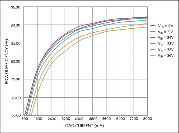
The reference design delivers a peak efficiency of 91.5% with the supplied components when the input is 24V. This general-purpose power solution can be used in many different types of power applications, such as programmable logic controllers (PLC), industrial process control, industrial sensors, telecom/datacom power supplies, isolated battery chargers, servers, and embedded computing.
MAXREFDES116 # Sistem Board Memperbesar +Lockout input-undervoltage (EN / UVLO) disediakan untuk pemrograman input-pasokan start tegangan (set ke 16.5V dalam desain) dan untuk memastikan operasi yang tepat saat kondisi brownout. EN / UVLO masukan juga digunakan untuk mengaktifkan / mematikan IC. Skema perlindungan tegangan input (OVI) disediakan untuk memastikan bahwa controller menutup ketika pasokan input melebihi nilai maksimum yang diperbolehkan (set ke 37.0V dalam desain). Untuk mengontrol lonjakan arus, perangkat menggabungkan soft-start (SS) pin untuk mengatur waktu soft-start untuk regulator. disipasi daya di bawah kondisi kesalahan diminimalkan oleh proteksi arus cegukan (modus cegukan). Lembut-stop fitur memberikan pemakaian yang aman dari kapasitor penjepit saat perangkat dimatikan, dan memungkinkan controller untuk memulai kembali dengan cara yang terkendali dengan baik. Selain itu, batas arus negatif disediakan di sirkuit saat-akal, membantu limit penjepit-switch saat dalam kondisi operasi yang dinamis. Sebuah kesalahan overtemperature memicu thermal shutdown untuk perlindungan yang handal dari perangkat. Desain referensi memberikan efisiensi puncak 91,5% dengan komponen yang disediakan ketika input 24V. solusi kekuasaan umum-tujuan ini dapat digunakan dalam berbagai jenis aplikasi daya, seperti pengendali programmable logic (PLC), kontrol proses industri, sensor industri, telekomunikasi / datacom pasokan listrik, pengisi daya baterai terisolasi, server, dan tertanam komputasi.
System Diagram
 Figure 1. The MAXREFDES116# reference design block diagram.
Detailed Circuit Description
Hardware Description
The MAX17599 low IQ active-clamp current-mode PWM controller contains all the control circuitry required for designing wide-input isolated forward converter industrial power supplies.
The MAX17599 low IQ active-clamp current-mode PWM controller contains all the control circuitry required for designing wide-input isolated forward converter industrial power supplies.
The device includes an AUX driver that drives an auxiliary MOSFET (clamp switch) that helps implement the active-clamp transformer reset topology for forward converters. This reset topology has several advantages, including reduced voltage stress on the switches, transformer size reduction due to larger allowable flux swing, and improved efficiency due to elimination of dissipative snubber circuitry. Programmable dead-time between the AUX and main driver allows for zero-voltage switching.
Diagram sistem
The MAXREFDES116 # desain referensi blok diagram.Figure 1. MAXREFDES116 # referensi blok desain diagram.
Rinci Circuit Deskripsi
hardware Description
The MAX17599 IQ rendah aktif-klem saat-mode PWM controller berisi semua sirkuit kontrol yang diperlukan untuk merancang lebar-masukan terisolasi maju konverter pasokan listrik industri.
Perangkat ini termasuk driver AUX yang mendorong MOSFET tambahan (penjepit switch) yang membantu melaksanakan aktif-penjepit transformator ulang topologi untuk konverter ke depan. Topologi ulang ini memiliki beberapa keuntungan, termasuk mengurangi stres tegangan pada switch, pengurangan ukuran trafo karena ayunan fluks yang lebih besar yang diijinkan, dan peningkatan efisiensi karena penghapusan sirkuit snubber disipatif. Programmable mati-waktu antara AUX dan sopir utama memungkinkan untuk nol-tegangan switching.
Primary Power Stage
The active-clamp transformer primary side is driven by an n-channel MOSFET (N1) and a p-channel MOSFET (P1). While N1 is on, power is delivered to the secondary, and magnetizing energy is being stored in the transformer. During this time, P1 is off, and the clamp capacitor (C12) is charged at a constant voltage level.
The active-clamp transformer primary side is driven by an n-channel MOSFET (N1) and a p-channel MOSFET (P1). While N1 is on, power is delivered to the secondary, and magnetizing energy is being stored in the transformer. During this time, P1 is off, and the clamp capacitor (C12) is charged at a constant voltage level.
When N1 turns off, the leakage and magnetizing currents charge up the drain-to-source capacitance of N1. Once the drain-to-source voltage of N1 exceeds the voltage across the clamp capacitor, the body diode of P1 begins to conduct. With the body diode of P1 conducting, the magnetizing current begins to charge the clamp capacitor.
After the body diode of P1 conducts, P1 turns on. This provides zero-current switching for the p-channel MOSFET. The clamp capacitor continues to charge until the magnetizing current is reduced to 0A. At this point, the magnetizing current reverses, and the clamp capacitor begins to discharge until the p-channel MOSFET turns off.
After P1 turns off, the clamp capacitor remains at a fixed voltage. There is a fixed delay before N1 turns on. During this delay, the energy in the parasitic components discharges the VDS of N1 towards VIN. This allows softer turn-on and lower switching losses for N1.
The MAX17599 NDRV pin drives the n-channel MOSFET while AUXDRV pin is level-shifted through C8, R15, and D3, and then drives the p-channel MOSFET.
Primer Daya Tahap Aktif-klem sisi transformator utama didorong oleh MOSFET n-channel (N1) dan MOSFET p-channel (P1). Sementara N1 adalah pada, kekuatan dikirimkan ke sekunder, dan energi magnetizing sedang disimpan dalam transformator. Selama ini, P1 adalah off, dan kapasitor penjepit (C12) dibebankan pada tingkat tegangan konstan. Ketika N1 mati, kebocoran dan arus magnetizing mengisi kapasitansi drain-to-sumber N1. Setelah tegangan drain-to-sumber N1 melebihi tegangan kapasitor penjepit, dioda tubuh P1 mulai melakukan. Dengan dioda tubuh P1 budidaya, arus magnetizing mulai mengisi kapasitor penjepit. Setelah dioda tubuh perilaku P1, P1 menyala. Ini memberikan nol-saat beralih untuk p-channel MOSFET. Klem kapasitor terus mengisi sampai saat ini magnetizing berkurang untuk 0A. Pada titik ini, membalikkan arus magnetizing, dan kapasitor penjepit mulai debit sampai p-channel MOSFET mati. Setelah P1 mematikan, klem kapasitor tetap pada tegangan tetap. Ada penundaan tetap sebelum N1 menyala. Selama penundaan ini, energi dalam komponen parasit debit VDS dari N1 menuju VIN. Hal ini memungkinkan lebih lembut turn-on dan switching rendah kerugian untuk N1
Secondary Power Stage
The secondary power stage consists of the synchronous rectifiers (N2, N3), and the output filters (L2, C11, C19, C20, C23).
The secondary power stage consists of the synchronous rectifiers (N2, N3), and the output filters (L2, C11, C19, C20, C23).
When N1 is on, N2 is on, while N3 is off. During this time, a voltage equal to the input voltage multiplied by the NS:NP turns ratio of the transformer is applied across N3; the inductor and the load capacitor are charged and being stored with energy.
When N1 is off, N2 is off, while N3 is on. During this time, the inductor current flows through N3 and continues transferring energy to the load capacitor.
The voltage on the input end of the filter inductor is a typical buck-converter square wave. The inductor and output capacitors filter the square wave to produce a DC voltage on the output.
Feedback Control Loop
The feedback network is typical of most isolated forward converters. It is constructed using a TLV431B programmable shunt regulator, a 3000V isolation optocoupler, and other RC components.
The feedback network is typical of most isolated forward converters. It is constructed using a TLV431B programmable shunt regulator, a 3000V isolation optocoupler, and other RC components.
Startup Voltage and Input Overvoltage Protection Setting (EN/UVLO, OVI)
The EN/UVLO pin in the MAX17599 serves as an enable/disable input, as well as an accurate programmable undervoltage lockout (UVLO) pin. The MAX17599 does not begin startup opera-tions unless the EN/UVLO pin voltage exceeds 1.21V (typ). The MAX17599 turns off if the EN/UVLO pin voltage falls below 1.15V (typ). A resistor divider from the input DC bus to ground can be used to divide down and apply a fraction of the input DC voltage to the EN/ UVLO pin. The values of the resistor divider can be selected so that the EN/UVLO pin voltage exceeds the 1.21V (typ) turn on threshold at the desired input DC-bus voltage. The same resistor divider can be modified with an additional resistor, (ROVI), to implement overvoltage input protection in addition to the EN/UVLO functionality. When the voltage at the OVI pin exceeds 1.21V (typ), the MAX17599 stops switching. Switching resumes with soft-start operation, only if the voltage at the OVI pin falls below 1.15V (typ). For the expected values of the startup DC-input voltage (VSTART) and input-overvoltage threshold (VOVI), the resistor values for the divider can be calculated as follows:
The EN/UVLO pin in the MAX17599 serves as an enable/disable input, as well as an accurate programmable undervoltage lockout (UVLO) pin. The MAX17599 does not begin startup opera-tions unless the EN/UVLO pin voltage exceeds 1.21V (typ). The MAX17599 turns off if the EN/UVLO pin voltage falls below 1.15V (typ). A resistor divider from the input DC bus to ground can be used to divide down and apply a fraction of the input DC voltage to the EN/ UVLO pin. The values of the resistor divider can be selected so that the EN/UVLO pin voltage exceeds the 1.21V (typ) turn on threshold at the desired input DC-bus voltage. The same resistor divider can be modified with an additional resistor, (ROVI), to implement overvoltage input protection in addition to the EN/UVLO functionality. When the voltage at the OVI pin exceeds 1.21V (typ), the MAX17599 stops switching. Switching resumes with soft-start operation, only if the voltage at the OVI pin falls below 1.15V (typ). For the expected values of the startup DC-input voltage (VSTART) and input-overvoltage threshold (VOVI), the resistor values for the divider can be calculated as follows:
VSTART = (R6 + R7 + R11)/(R6 + R7) × 1.21 (V)
VOVI = (R6 + R7 + R11)/R6 × 1.21 (V)
If R6 = 24kΩ, R7 = 30kΩ, and R11 = 680kΩ, then:
VSTART = 16.5V, VOVI = 37.0V.
These values give a safe margin for input-voltage range of 17V to 36V.
Quick Start Guide
Required Equipment:
- MAXREFDES114#
- One adjustable DC power supply with voltage output up to 37V and current up to 3A
- One electronic load
- Two voltmeters
- Two ammeters
Procedue
The MAXREFDES116# board is fully assembled and tested. Use the following steps to verify board operation.
- Turn off the power supply.
- Connect the positive terminal of the power supply to the VIN connector of the MAXREFDES116# board.
- Connect the PGND connector of the MAXREFDES116# board to the positive terminal of one ammeter. Connect the negative terminal of the ammeter to the negative terminal of the power supply.
- Connect one voltmeter across the VIN and the PGND connectors of the MAXREFDES116# board.
- Connect the VOUT connector of the MAXREFDES116# board to the positive terminal of the electronic load.
- Connect the negative terminal of the electronic load to the positive terminal of the second ammeter. Connect the negative terminal of the ammeter to the GNDO connector of the MAXREFDES116# board.
- Connect the second voltmeter across the VOUT and the GNDO connectors of the MAXREFDES116# board.
- Turn on the power supply. Set the output to 24V.
- Set the electronic load to a constant current between 0A to 8A.
- Verify the second voltmeter reading is ±0.25V.
Lab Measurements
The MAXREFDES116# was verified and tested under full input range and different output load conditions. The power efficiency vs. load current is illustrated in Figure 2.
Tahap Daya sekunder Tahap daya sekunder terdiri dari penyearah sinkron (N2, N3), dan filter keluaran (L2, C11, C19, C20, C23).Ketika N1 aktif, N2 aktif, sedangkan N3 adalah off. Selama ini, tegangan sama dengan tegangan input dikalikan dengan NS yang: NP ternyata rasio transformator diterapkan di N3; induktor dan beban kapasitor dibebankan dan disimpan dengan energi. Ketika N1 adalah off, N2 mati, sedangkan N3 adalah pada. Selama ini, induktor arus mengalir melalui N3 dan terus mentransfer energi ke beban kapasitor. Tegangan di ujung input filter induktor adalah buck-converter gelombang persegi khas. Induktor dan output kapasitor menyaring gelombang persegi untuk menghasilkan tegangan DC pada output.Masukan Kontrol loop Jaringan umpan balik khas dari sebagian besar konverter maju terisolasi. Hal ini dibangun menggunakan TLV431B diprogram shunt regulator, sebuah 3000V isolasi optocoupler, dan komponen lainnya RC. Tegangan startup dan Input Perlindungan Tegangan Pengaturan (EN / UVLO, OVI) EN / UVLO pin di MAX17599 yang berfungsi sebagai mengaktifkan / menonaktifkan input, serta diprogram lockout undervoltage (UVLO) pin akurat. MAX17599 tidak dimulai startup opera-tions kecuali tegangan pin EN / UVLO melebihi 1.21V (typ). MAX17599 mati jika tegangan pin EN / UVLO turun di bawah 1.15V (typ). Sebuah pembagi resistor dari input DC bus ke tanah dapat digunakan untuk membagi bawah dan menerapkan sebagian kecil dari input DC tegangan ke pin EN / UVLO. Nilai-nilai pembagi resistor dapat dipilih sehingga tegangan pin EN / UVLO melebihi 1.21V (typ) giliran di ambang pada input yang diinginkan tegangan DC-bus. Pembagi resistor yang sama dapat dimodifikasi dengan resistor tambahan, (Rovi), untuk menerapkan perlindungan masukan tegangan selain fungsi EN / UVLO. Ketika tegangan di pin OVI melebihi 1.21V (typ), MAX17599 berhenti beralih. Switching resume dengan operasi soft-start, hanya jika tegangan pada pin OVI turun di bawah 1.15V (typ). Untuk nilai-nilai yang diharapkan dari tegangan startup DC-masukan (VSTART) dan input-tegangan threshold (VOVI), nilai-nilai resistor untuk pembagi dapat dihitung sebagai berikut:
VSTART = (R6 + R7 + R11) / (R6 + 7) × 1,21 (V) VOVI = (R6 + R7 + R11) / R6 × 1,21 (V) Jika R6 = 24kΩ, R7 = 30kΩ, dan R11 = 680kΩ, maka: VSTART = 16.5V, VOVI = 37.0V. Nilai-nilai ini memberikan margin yang aman untuk berbagai masukan tegangan dari 17V ke 36V. Panduan Ringkas Peralatan yang dibutuhkan:
MAXREFDES114 # Satu adjustable power supply DC dengan output tegangan sampai 37V dan arus hingga 3A Satu beban elektronik dua voltmeter dua amperemeter ProcedueThe MAXREFDES116 # papan sepenuhnya dirakit dan diuji. Gunakan langkah-langkah berikut untuk memverifikasi operasi forum.
 Figure 2. Power efficiency vs. load current.
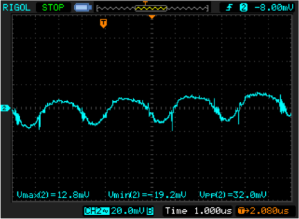
Figure 3 displays the output ripple at full load when the input is 24V
 Figure 3. Output ripple at 8A load.
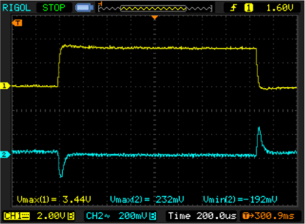
Figure 4 displays the load transient response when the load is stepped from 5mA to 3.2mA, and then dropped back to 5mA again. The input is 24V.
 Figure 4. Transient response when load steps from 5mA to 3.2A.
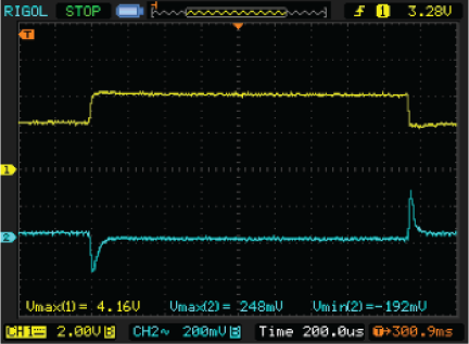
Figure 5 shows the load transient response when the load is stepped from 4.8A to 8A, and then dropped back to 4.8A again. The input is 24V.


Tidak ada komentar:
Posting Komentar